This work should be performed by trained maintenance engineers or compressed air system technicians. Improper piping by untrained personnel routinely causes oil contamination of the desiccant bed, condensate slugging of the towers, and moisture carry-over into production lines — problems that are expensive to diagnose and often irreversible without partial system rebuild.
The consequences of getting it wrong are concrete: oil contamination permanently destroys desiccant media, missing bypass lines force complete system shutdowns during routine maintenance, and undetected condensate slugs cause dew point failures that only surface after downstream equipment is already damaged.
This guide covers the complete piping of a desiccant dryer system — from site preparation and material selection through the installation sequence, post-installation validation, and fixes for the three most common commissioning failures.
Key Takeaways
- Install components in strict sequence: pre-filter → dryer → post-filter, with sloped piping and drain legs throughout
- Stainless steel is the preferred upstream pipe material for oil-free systems; aluminum is the right choice downstream
- A three-valve bypass line is required on any installation that cannot tolerate downtime during dryer maintenance
- Condensate slugs are the leading cause of desiccant bed damage; sloped inlet piping and automatic drain legs are the primary defense
- Dew point validation with a calibrated meter is required before the system enters full production service
Installation Guide for Desiccant Dryer Piping Systems
A desiccant dryer piping installation breaks into four distinct phases: site and system preparation, upstream inlet piping and filtration, downstream outlet piping and filtration, and auxiliary connections (drains, vents, bypass, controls). Cutting corners on any phase creates reliability problems that surface only after the system is in production — often at the worst possible time.
A typical single-dryer installation in a mid-size industrial facility requires one to two days for a two-person technical team. Heated desiccant dryers with blower and heater piping — such as the ZEKS Eclipse ZHA or ZBA series available through Comp-Air Ohio — may require additional time and coordination with electrical trades given heater power requirements ranging from 2.0 kW to 12.0 kW depending on model.
Prerequisites and Safety Considerations
Before piping work begins, the following site conditions must be confirmed:
- Compressor, aftercooler, and receiver are installed and operational
- Ambient temperature in the dryer room falls within the dryer's rated range (typically 40°F to 120°F for heatless desiccant units)
- Sufficient clearance exists on all sides of the dryer for piping access and future maintenance
Compatibility checks to complete before proceeding:
- Verify the dryer's rated inlet flow, pressure, and temperature against actual compressor output
- Confirm planned pipe sizes will maintain adequate velocity without excessive pressure drop — CAGI states well-designed systems should have no more than 10% pressure drop between compressor and point of use
- Check that purge exhaust and condensate drain connections match planned discharge routing
Hard stops — do not proceed if:
- Inlet air temperature will regularly exceed the manufacturer's rated maximum (120°F for most heatless desiccant systems)
- Pre-filtration is not yet in place
- Any piping materials are not rated for the system's maximum working pressure
Safety requirements: Depressurize and lockout/tagout all existing compressed air lines before making tie-in connections. Desiccant dust causes respiratory irritation — wear appropriate PPE when handling media or opening tower vessels during installation.
Tools and Materials Required
Essential tools:
- Pipe cutter or saw appropriate for the pipe material
- Pipe threader or compression fitting tools
- Torque wrench
- Pressure gauge with test port fittings
- Leak detection solution or electronic leak detector
- Calibrated dew point meter for post-installation validation
Required materials and components:
- Coalescing pre-filter (rated for oil aerosol removal)
- Particulate post-filter (to capture desiccant fines)
- Isolation valves upstream and downstream
- Bypass valve and bypass line piping
- Flexible anti-vibration connector for compressor-to-inlet piping
- Condensate drain lines and automatic drain valves
- Pressure and temperature gauges at inlet and outlet
Specialized tools — orbital welding equipment for stainless steel piping, calibrated dew point analyzers — may require rental or subcontracting. Don't substitute uncalibrated gauges or skip the dew point meter at commissioning.
Piping Material Selection and Layout Requirements
Upstream (inlet) side: For oil-free compressed air systems, stainless steel is the preferred material upstream of the dryer. Aluminum and stainless steel are identified by CABP as the appropriate smooth, corrosion-resistant materials for ISO 8573-1-oriented system design. Galvanized steel corrodes and creates rough internal surfaces that increase both contamination risk and pressure drop.
In facilities with chemically corrosive atmospheres, avoid copper with silver-soldered joints even where local codes permit. Joint degradation in such environments is a documented failure mode.
Downstream (outlet) side: Once air has passed through the post-filter, aluminum piping is the correct choice. Gardner Denver's Quick-Lock system (14mm–63mm) and Big-Lock system (70mm–273mm), both available through Comp-Air Ohio, are rated to 300 PSI and 300°F and carry a lifetime warranty. Both systems offer push-to-connect or clamp-to-connect installation. The AIGNEP INFINITY system is another available option, featuring a patented water trapping system for enhanced moisture management at the distribution level.
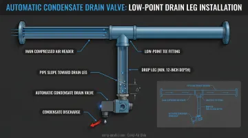
Pipe slope and drain legs: All inlet piping must slope continuously toward the dryer or toward dedicated low-point drains so condensate cannot pool and slug the pre-filter or desiccant bed. Include a drain leg with automatic condensate drain at the lowest point of any extended horizontal inlet run. Failing to slope piping is one of the most common field errors, particularly in retrofits. Verify specific slope requirements with the dryer manufacturer's installation guidelines.
Dryer positioning relative to the receiver:
| Position | Primary Advantage | Primary Drawback |
|---|---|---|
| After receiver | Lower condensate load, lower inlet temperature | Receiver exposed to wet air without protection |
| Before receiver | Protects receiver from internal corrosion | Dryer sees hotter, more saturated inlet air |
| Between two receivers | Best for high-variability demand | Requires additional receiver investment |
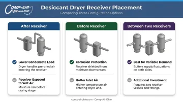
For critical instrument air systems or facilities with highly variable demand, placing both a wet receiver before and a dry receiver after the dryer is the most reliable configuration.
Bypass line and isolation valve configuration: Every industrial desiccant dryer installation requires a full bypass line. The standard arrangement uses three valves:
- Inlet isolation valve
- Outlet isolation valve
- Bridging bypass valve
Check valves downstream of dryers can create dangerous pressure-dump scenarios if a dryer valve fails. Pressure-sensing trip valves set to close on falling pressure are the more reliable protection approach.
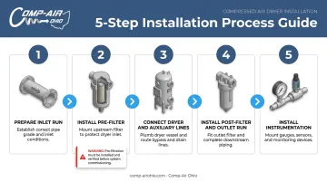
How to Pipe a Desiccant Dryer: Step-by-Step
The piping sequence must follow a defined order. Commissioning without pre-filtration in place permanently damages the desiccant media and voids most manufacturers' warranties. CAGI confirms that oil aerosols coat regenerative desiccant and render it useless if upstream filtration is inadequate.
Step 1 — Prepare the inlet run
- Run the inlet pipe from the compressor discharge (or aftercooler outlet) to the dryer inlet location
- Install the anti-vibration flexible connector directly at the compressor outlet to isolate pipe-borne vibration
- Slope the inlet run continuously toward the dryer
- Install a drain leg with automatic condensate drain at the lowest point if the horizontal run exceeds the dryer manufacturer's specified distance
Step 2 — Install the pre-filter
- Mount the coalescing pre-filter in the inlet line immediately upstream of the dryer inlet connection
- Verify filter orientation — most coalescing filters are directional
- Connect the filter's automatic condensate drain to the facility's condensate management system
- ZEKS Eclipse dryers include factory-matched filter packages (GP grade pre-filtration achieving ISO Class 2 for solids and oil) sized and certified together as an integrated system
Step 3 — Connect the dryer and auxiliary lines
- Connect the pre-filtered inlet line to the dryer's wet air inlet port
- Connect the dryer's dry air outlet port to the downstream post-filter inlet
- Route the purge exhaust port to a suitable outdoor or ventilated discharge location; install a silencer if required
- Connect condensate drain ports to the condensate management system
- For heated or blower-purge type dryers (ZHA or ZBA series), complete heater and blower piping connections per manufacturer wiring and piping diagrams
Step 4 — Install the post-filter and outlet run
- Mount the particulate post-filter immediately downstream of the dryer outlet
- ZEKS designates the ZFF Flanged Filter Grade G as the recommended after-filter for heatless desiccant dryer applications
- Connect the post-filter outlet to the downstream distribution header
- Install the outlet isolation valve and integrate bypass line connection points at both the inlet and outlet isolation valves
Step 5 — Install instrumentation and finalize connections
- Install pressure gauges at the dryer inlet and outlet for differential pressure monitoring
- Install inlet temperature gauge
- Install a dew point sampling port downstream of the post-filter — or a permanent dew point sensor if continuous monitoring is required
- Torque all flanged and threaded connections to specification
- Apply thread sealant compatible with compressed air service on all threaded joints
With all five steps complete, the system is ready for pre-service validation.
Post-Installation Checks and Validation
Before the dryer enters full production service, every connection must be leak-tested and functional operation confirmed. Skipping this step leads to delayed failures: moisture breakthroughs that only surface after downstream equipment damage has already occurred.
Leak test procedure:
- Pressurize the system slowly to working pressure
- Apply leak detection solution to all joints, flanges, threaded connections, and condensate drain fittings
- Identify and repair all leaks before proceeding
- Minor leaks on the outlet (dry air) side reintroduce moisture and degrade dew point performance
Dew point validation: Allow the dryer to complete a minimum of two to three full adsorption/regeneration cycles before measuring outlet dew point (follow the specific dryer manual — BEKO's XC series, for example, runs the first five cycles as short cycles without dew point validation). Use a calibrated dew point meter at the outlet sampling port to confirm the achieved pressure dew point (PDP) matches the dryer's rated specification.
Indicators of correct installation:
- Stable cycling of tower switching valves
- No condensate backflow at the pre-filter drain
- Consistent purge exhaust flow from the regeneration vent
- Outlet PDP at or better than rated specification (ISO 8573-1 Class 2 = -40°C PDP; Class 1 = -70°C PDP)
Common Piping Installation Problems and Fixes
Most piping installation failures follow recognizable patterns. Catching them at commissioning — rather than after a production disruption — is the difference between a one-day fix and a partial system rebuild.
Condensate Slugging the Desiccant Bed
Problem: Liquid water enters the desiccant tower in slugs, rapidly saturating the media and causing dew point failure shortly after startup.
Likely causes:
- Inlet piping not sloped toward a drain leg
- No moisture separator or pre-cooler installed upstream
- High temperature differential between compressor discharge and ambient, causing condensation in the inlet run before the pre-filter
Install a drain leg with automatic drain at the inlet pipe low point. The ZEKS SDD200H pneumatic drain (a zero-loss drain carried by Comp-Air Ohio) is a reliable option: it expels no compressed air when cycling and handles up to 80% oil/water mixtures without clogging.
If temperature differentials are significant, add a mist eliminator or knockout pot upstream of the pre-filter and insulate the piping between the pre-filter and the desiccant vessel inlet.
Excessive Pressure Drop Across the Dryer
Problem: System pressure at the dryer outlet is noticeably lower than at the inlet, reducing downstream tool and equipment performance.
Likely causes:
- Pipe diameter undersized for the actual flow rate
- Pre-filter or post-filter elements clogged due to missed maintenance
- Dryer sized at compressor's rated pressure but operating at a lower average pressure, reducing effective capacity
Address pressure drop with these steps:
- Verify actual average operating pressure against the dryer's rated inlet pressure
- Upsize connecting pipe if air velocity is excessive
- Establish a filter replacement schedule
- When re-sizing, select the next dryer size up from the calculated requirement
CAGI notes that every 2 psi increase in discharge pressure increases energy consumption by approximately 1%. Undersized piping that forces system pressure up compounds this cost daily.
Dew Point Spike During Tower Switching
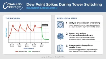
Problem: Outlet dew point rises sharply at regular intervals coinciding with the dryer's tower switching cycle, causing intermittent moisture excursions into the distribution system.
Likely causes:
- Towers switching before the regenerated tower is fully re-pressurized
- Desiccant media partially oil-contaminated, reducing adsorption capacity
- Multiple parallel dryers with unsynchronized switching cycles compounding the spikes
To resolve switching spikes:
- Confirm the re-pressurization phase completes fully before switching; check and adjust the dryer controller's cycle timing
- Inspect desiccant for oil contamination and replace if necessary
- If multiple dryers are paralleled, stagger their switching events to prevent simultaneous spikes
Pro Tips for Installing Desiccant Dryer Piping Effectively
Sequencing and Timing
Never connect or commission the desiccant dryer before all pre-filtration is fully in place and operational. If the facility is being built in stages, cap the dryer inlet port and bypass filtered air around the dryer until pre-filters are installed and verified. Skipping this step is one of the most expensive commissioning mistakes to correct after the fact.
Cold Climate Considerations
For Northern Ohio installations in unheated enclosures, cold ambient temperatures can undermine heatless regeneration efficiency. Address this with three precautions:
- Insulate desiccant towers to contain heat and maintain regeneration performance (available as an option on ZEKS Eclipse dryers)
- Add heat-tracing on tower exteriors in severely cold environments
- Store desiccant media in sealed containers until the moment of loading to prevent premature moisture absorption
Documentation at Commissioning
Record inlet pressure, inlet temperature, outlet pressure, and outlet dew point at commissioning. Retain these as your baseline performance record. Any future deviation from these values during routine operation is the earliest indicator of a developing piping or media problem.
Gardner Denver-certified systems supported by Comp-Air Ohio include controller options with maintenance reminders and dew point monitoring. Document the initial readings from these displays as your commissioning baseline.
When to Bring in a Specialist
Good commissioning documentation also makes it easier to hand off to a specialist when one is required. Heated desiccant dryers with blower purge involve electrical integration, precise heater piping, and blower alignment — these require factory-trained technicians, not in-house maintenance staff.
Any installation into a pharmaceutical, food-grade, or NFPA 99 medical air system should be validated by a certified compressed air specialist. Comp-Air Ohio's EnviroAire scroll systems are specifically designed for NFPA 99 and CSA code compliance in medical air applications, with integrated dew point and carbon monoxide monitoring built in.
Frequently Asked Questions
What is the best piping for compressed air?
For upstream (wet) piping ahead of a desiccant dryer, stainless steel is preferred — it prevents rust particulate from contaminating the desiccant bed or clogging the pre-filter. Downstream of the post-filter, aluminum piping (such as Gardner Denver Quick-Lock or AIGNEP INFINITY) offers lightweight, corrosion-resistant distribution well-suited to dry air at low dew points.
Should a desiccant dryer be installed before or after the air receiver?
Post-receiver placement is most common: it lowers condensate load and inlet temperature. Pre-receiver placement protects the tank from internal corrosion. For critical instrument air or high-variability demand, the most reliable setup positions the dryer between two receivers — wet upstream, dry downstream.
Do desiccant dryers require both pre-filters and post-filters?
Pre-filtration (coalescing filter) is mandatory — oil aerosols coat desiccant media and permanently destroy adsorption capacity, per CAGI. Post-filtration (particulate filter) is required for bead-based desiccant dryers to capture desiccant fines that enter the air stream through attrition during normal operation.
How do you prevent condensate slugs from damaging desiccant media?
Slope inlet piping continuously toward drain legs and install an automatic condensate drain at the low point. Where compressor discharge temperature significantly exceeds ambient, add a mist eliminator or knockout pot upstream of the pre-filter to intercept condensation before it reaches the desiccant bed.
What pipe slope is recommended for desiccant dryer inlet piping?
A slope of ¼" per foot (1:48) toward the dryer or a dedicated drain leg is the standard baseline for compressed air inlet piping. Confirm the exact minimum slope with your dryer manufacturer's installation guidelines, as requirements vary by unit size and inlet run length.
When is a bypass line required on a desiccant dryer installation?
Any facility that cannot interrupt production airflow for dryer maintenance requires a bypass line — meaning most industrial installations. The standard configuration uses inlet and outlet isolation valves with a bridging bypass valve, so the dryer can be fully isolated and serviced without shutting down the compressed air system.
