According to CAGI, simply summing the full-load CFM ratings of all your air-using equipment produces a grossly overstated demand figure — and yet undersized systems remain one of the most common causes of unexplained CNC machine faults in production shops.
This guide covers the core functions of compressed air in CNC machines, how to size your system correctly, air quality requirements, compressor selection, and piping design — practical information for Northern Ohio machine shops making compressed air decisions.
Key Takeaways
- Most CNC machines require 80–100 PSI minimum at the machine inlet, but your compressor outlet must be set higher to cover system pressure losses
- Size your receiver tank generously — it absorbs tool-change demand spikes the compressor can't respond to fast enough
- Most CNC shops need a refrigerated dryer plus two-stage filtration at minimum — ISO 8573-1 is the standard that defines those air quality targets
- VFD compressors that hold delivery pressure within ±1.5 PSI make a measurable difference in clamping consistency and surface finish quality
- Deferred air system maintenance shows up first as mystery CNC faults, not obvious compressor failures
Why CNC Machine Shops Run on Compressed Air
Compressed air in a CNC machining center isn't a single function: it covers five concurrent systems, each with its own pressure and flow demands.
Spindle Tool Clamping and Drawbar Operation
The drawbar mechanism that locks tool holders into the spindle taper is pneumatically actuated. Haas mills, for example, require 100 PSI minimum at the pressure regulator input, with the main regulator set to 85 PSI. During tool release, Haas service documentation specifies that a pressure drop greater than 10 PSI indicates a supply restriction. Inadequate system capacity can directly weaken clamping force, not just slow the tool change.
A tool that isn't fully seated in the taper is a safety hazard — and in a production environment, the risk is real.
Pneumatic Workholding
Pneumatic chucks and vises depend on consistent line pressure to hold parts against cutting forces. Small pressure fluctuations (the kind a fixed-speed compressor creates as it cycles between load and unload) can allow workpiece movement that pushes dimensional tolerances out of spec. On tight-tolerance jobs, this is a process control problem, not just an equipment problem.
Chip and Coolant Management
Multiple air nozzles run simultaneously to clear chips from cutting surfaces, guide ways, and tooling. Sticky aluminum or fine cast iron dust requires sustained airflow. Standard Haas vertical mills carry these compressed air demands:
- 4 SCFM for the base machine
- +2 SCFM when the air nozzle option is installed
- 9 SCFM for high-speed and extended-capacity models
When several nozzles fire simultaneously, the instantaneous demand spike can be several times the machine's average consumption.
Automatic Tool Change (ATC) Systems
ATCs concentrate the most pneumatic cylinders in one place: magazine indexing, robot arm, clamping and unclamping all operate in rapid sequence. This creates the highest instantaneous demand events in a typical CNC shop.
No manufacturer publishes an industry-standard peak-to-average CFM ratio for ATC events, which is exactly why receiver tank sizing matters. You need stored volume to absorb the spike, not a compressor fast enough to match it in real time.
Spindle Air Purge
A low-volume but continuous airflow maintains positive pressure inside high-speed spindle bearings, blocking coolant mist and fine particles from reaching the bearing surfaces. Haas specifies the following purge pressures:
- 17 PSI for standard spindles
- 20 PSI for 15,000 RPM spindles
Interrupting this airflow, even briefly, allows contamination to enter. For that reason, the purge supply line should run on a dedicated regulator, independent of the main machine air circuit.
Calculating Your Shop's Compressed Air Needs
Reading Equipment Manuals and Applying Safety Margins
Start with each machine's OEM documentation. Manufacturer CFM figures represent design-point consumption; real-world demand varies based on cutting conditions, fixturing cycles, and nozzle usage. Apply a design margin above the rated values — a common approach is 10–15% above your calculated total — to account for that variation and for future system additions.
Pay attention to whether a manual lists average or peak consumption. For ATC-intensive machines like horizontal machining centers, the Mazak HCN series requires 350–700 L/min (12–25 CFM) depending on model, which reflects sustained flow demand during active operation.
Once you have per-machine figures, the next step is accounting for the fact that not all machines run at full demand simultaneously.
Simultaneity Factor for Multi-Machine Shops
Not every machine in your shop is cutting, clamping, and changing tools at the same instant. A simultaneity (diversity) factor accounts for this reality. Rather than summing every machine's full-load CFM rating, you apply a usage factor to each air-consuming device based on how often it's actually drawing air.
CAGI confirms that summing all rated CFM values produces a grossly overstated total and recommends a demand inventory approach instead. As a practical guideline:
- 3-machine shop: demand events are sparse, diversity factor stays relatively high
- 10-machine shop: more overlap in demand cycles, diversity factor decreases
- 20+ machines: factor approaches 0.5–0.6 for most shop layouts
System Pressure Drop Budget
Your compressor outlet pressure must be set higher than any machine's minimum requirement because pressure drops at every component between the compressor and the machine inlet:
| System Component | Typical Pressure Loss |
|---|---|
| Refrigerated dryer | 2–3 PSI |
| Main line coalescing filter | 1–3 PSI |
| Distribution piping | 3–5 PSI |
| Point-of-use filter/regulator | 2–3 PSI |
| Total possible loss | 8–14+ PSI |
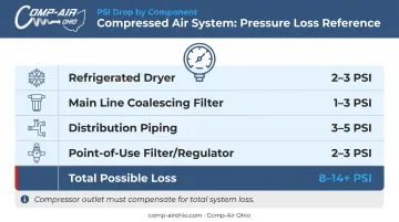
CAGI's pressure drop guidelines set a benchmark of no more than 10% total pressure drop between compressor discharge and point of use. For a machine requiring 90 PSI at the inlet, your compressor outlet may need to run at 105–110 PSI to guarantee that minimum under load.
Air Receiver Tank Sizing
A compressor cannot respond fast enough to instantaneous demand spikes. The receiver tank is what prevents pressure collapse during an ATC cycle or a simultaneous nozzle demand event. The Compressed Air Challenge provides a receiver sizing formula:
V = T × (C − S) × Pa / (P1 − P2)
Variables defined:
- V — receiver volume (gallons)
- T — event duration (minutes)
- C — event demand (CFM)
- S — metered supply (CFM)
- Pa — atmospheric pressure (14.7 PSIA)
- P1 / P2 — initial and final pressures (PSIG)
The key variable is accurate event CFM — measure it directly or obtain it from the OEM rather than estimating.
Size conservatively. A larger receiver costs less than a ruined workpiece or a spindle bearing failure.
Fixed-Speed vs. VFD Pressure Stability
Fixed-speed compressors cycle between load and unload, creating a 10–15 PSI pressure band at the machine end. That oscillation affects workholding consistency and finish machining quality. CAGI data shows that variable speed drive (VSD) compressors hold delivery pressure within ±1.5 PSI — a meaningful difference for precision work.
Gardner Denver's LRS Series VFD compressors are rated for 30–50% energy savings compared to fixed-speed equivalents by matching motor speed to actual demand. In a CNC shop where air demand fluctuates throughout the shift, that translates directly to lower monthly energy costs.
Compressed Air Quality Standards for CNC Machining
ISO 8573-1 and What It Means for CNC Shops
ISO 8573-1:2010 classifies compressed air quality across three contaminant categories: solid particles, moisture (measured as pressure dew point), and oil content. CNC machine OEMs typically specify "clean, dry air" without citing a specific ISO class — which means the shop owner must match air quality to the most sensitive application in the system.
Moisture Control: Refrigerated vs. Desiccant
Water vapor in compressed air condenses as the air cools downstream. In a CNC environment, that moisture:
- Emulsifies pneumatic cylinder lubricant
- Accelerates seal wear
- Contaminates spindle purge air and reaches bearings
- Freezes distribution lines in unheated bays during Ohio winters
Refrigerated dryers achieve a +38°F pressure dew point, aligning with ISO Class 4 — adequate for climate-controlled shops where piping stays above freezing. ZEKS refrigerated dryers from Comp-Air Ohio's lineup cover 10 - 19,200 CFM with True-Cycling operation that maintains consistent dew point performance.

For shops with unheated areas, outdoor piping runs, or any process requiring a lower dew point, a desiccant dryer is the right call. ZEKS desiccant models achieve −40°F standard (ISO Class 2), with optional −80°F or −100°F configurations for critical applications. When ambient temperatures in Northern Ohio drop below freezing, a desiccant dryer is the only reliable protection against frozen lines that shut down production.
Oil Contamination from Oil-Flooded Compressors
A lubricated rotary screw compressor introduces 2–10 ppm by weight of oil carryover into the air stream. In a CNC pneumatic system, that oil:
- Impairs solenoid valve operation
- Contaminates air seals and O-rings
- Disrupts lubrication ratios in pneumatic cylinders
- Causes accelerated valve wear that compounds over time
Two-stage filtration addresses all four: a main line coalescing filter drops oil content to below 0.1 mg/m³, followed by a point-of-use precision filter at each machine. ZEKS ZFF high-efficiency filter elements available through Comp-Air Ohio achieve 0.01 ppm oil carryover, meeting ISO Class 1 oil requirements.
The FRL (filter-regulator-lubricator) unit on each CNC machine is designed to catch residual contamination — not to compensate for inadequate upstream filtration. Don't treat it as your primary oil removal device.
Solid Particle Contamination
Solid particle contamination ties directly to oil filtration gaps — both failures tend to surface as intermittent machine faults rather than clear diagnostic codes. Common particle sources include:
- Airborne dust entering the compressor intake
- Pipe scale and rust from older steel distribution lines
- Desiccant powder migration from dryer beds
- Degraded filter media breaking down over time
Micron-scale particles jam precision regulators and proportional valves. Proper upstream filtration prevents this. CAGI recommends replacing filter elements when differential pressure exceeds 5–7 PSI, or at six-month intervals — whichever comes first.
Rotary Screw vs. Piston: Choosing the Right Compressor Type for CNC Shops
Rotary Screw Compressors: The CNC Shop Standard
For production CNC environments, rotary screw compressors are the correct choice. The reasons are practical:
- Continuous duty cycle — no mandatory cool-down periods between load cycles, unlike reciprocating piston machines rated for 50–75% duty cycles
- Stable pressure output — especially with VFD control
- Lower noise levels — suitable for indoor installation near operators
- Longer service intervals — fewer scheduled stops compared to piston compressors
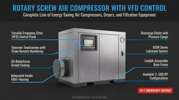
Gardner Denver's LRS Series VFD rotary screw compressors (7–290 kW, 29–1,620 CFM at 75–190 PSIG) are a common fit for multi-machine CNC shops. The Governor touchscreen controller provides real-time pressure and discharge monitoring. The iConn remote connectivity adds diagnostic alerts, so shops catch pressure anomalies before they trigger a machine alarm.
Oil-Free vs. Oil-Flooded: When Does It Matter for CNC?
Most general-purpose CNC machining shops can meet required air quality standards with a well-maintained oil-flooded rotary screw compressor and proper two-stage filtration. Oil-free compressors carry a higher capital cost and are not necessary for typical job shop or production machining work.
That changes when your customers specify air quality requirements. Shops producing parts for aerospace, medical device, or semiconductor applications may face contractual or regulatory requirements for ISO 8573-1 Class 0 oil-free air — a level that oil-flooded compressors with filtration cannot certifiably guarantee.
Gardner Denver's EnviroAire Series covers this requirement across multiple capacity ranges:
- EnviroAire S/ES (3–10 HP, 8–126 CFM) — oil-less rotary scroll, ISO Class 0 certified
- EnviroAire VS (15–110 kW, variable speed, water-injected screw) — ISO Class 0 certified
- EnviroAire T/TVS (75–315 kW, two-stage oil-free screw) — ISO Class 0 certified, silicone-free
For shops without Class 0 requirements, oil-flooded with proper filtration remains the practical starting point — and the right dryer and filter selection will determine whether that system actually performs to spec.
Piping, Installation, and System Design for Multi-Machine Shops
A correctly sized compressor paired with undersized or poorly designed distribution piping will still produce pressure problems at the machine. Piping deserves as much attention as the compressor selection.
Ring Main vs. Branch Layout
A ring main (loop) layout routes the main distribution header in a closed loop around the shop. Each machine drop connects to the loop at the nearest point, and air can arrive from either direction. Advantages:
- Pressure balances naturally across all drop points
- Individual sections can be isolated for maintenance without shutting down production
- The layout accommodates future machine additions more easily than a branch system
A tree/branch layout is simpler to install but creates pressure imbalances as machine count grows, with drops at the far end of the branch seeing the most pressure loss.
Pipe Sizing and Material Selection
CAGI recommends maintaining pipe velocity at 20 ft/s or lower to minimize turbulence-driven pressure drop. Pressure drop rises with the square of flow rate — doubling flow through an undersized pipe creates far more than twice the pressure loss. Size distribution headers generously from the start.
Material choice affects both longevity and pressure performance. Aluminum quick-connect piping systems offer:
- Smooth internal walls that resist corrosion and particle generation
- No rust, no thread tape debris, no pipe dope contamination
- Faster installation than galvanized steel
- Corrosion-related leaks in steel systems can appear as quickly as six months after installation
For Northern Ohio machine shops, Comp-Air Ohio carries the AIGNEP INFINITY system (20–168mm diameter) and Gardner Denver's Quick-Lock and Big-Lock systems (½" to 10" diameter, rated 300 PSI). Both options include complete system design and installation support, from the compressor room to individual machine drop points.
Each machine branch should include its own shutoff valve so a single machine can be serviced without affecting shop-wide production.
Maintenance Essentials for CNC Shop Air Systems
Routine Tasks That Protect CNC Performance
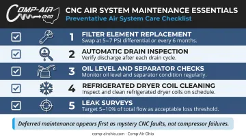
Deferred maintenance on compressed air systems rarely announces itself as a compressor failure. It shows up first as mystery CNC faults: pressure alarms, slow tool changes, intermittent clamping problems. By the time the compressor logs a fault, the machines have been running in degraded conditions for weeks.
Key routine tasks:
- Filter element replacement — swap elements when differential pressure exceeds 5–7 PSI, or every six months regardless; a clogged element creates pressure drop, a failed element provides zero filtration
- Automatic drain inspection — verify drains are actually discharging; stuck-closed drains flood downstream components with liquid water
- Oil level and separator checks on oil-flooded machines — degraded separator elements increase oil carryover
- Refrigerated dryer coil cleaning — fouled coils raise dew point and allow moisture into the system
- Leak surveys — DOE research shows poorly maintained systems waste 20–30% of compressor output through leaks; a reasonable target is below 5–10% of total flow
Comp-Air Ohio provides scheduled preventive maintenance programs and 24/7 emergency service for contract customers across Northern Ohio — a direct option for shops that need guaranteed priority response when something fails on second shift.
Periodic System Audits
Routine maintenance catches task-level failures, but it won't tell you whether the system is still sized for your current load. CNC shops grow — a system configured for three machines in 2018 may be struggling under six today. A basic audit covers:
- Pressure mapping at machine inlets — what pressure are machines actually receiving under load?
- Leak detection — ultrasonic surveys identify losses invisible to the ear
- Receiver sizing validation — confirm stored volume is adequate for current ATC demand events
- Piping velocity check — additions to the system can push header segments past the 20 ft/s threshold without anyone noticing
Audits are most valuable before expansion. Running one before adding a new CNC machine costs a fraction of what you'll spend diagnosing pressure problems after installation — or retrofitting undersized piping you just ran.
Frequently Asked Questions
What PSI do CNC machines typically require?
Most CNC machining centers specify 80–100 PSI minimum at the machine inlet (Haas requires 100 PSI, Hurco specifies 80–100 PSI, Mazak HCN models range from 73–131 PSI). Because distribution systems lose 10–15+ PSI between the compressor outlet and the machine inlet, set your compressor to 105–115 PSI to guarantee those minimums under production load.
What size air compressor do I need for a CNC machine shop?
Sizing depends on machine count, each machine's rated CFM, and a simultaneity factor reflecting that not all machines peak simultaneously. Pull CFM values from each OEM manual, apply a usage factor, add a 10–15% design margin, and consult a compressed air specialist for multi-machine installations.
Do I need an air dryer for my CNC machine shop?
Yes. Moisture in compressed air damages pneumatic cylinders, accelerates seal and O-ring wear, and can contaminate spindle bearings through the purge air supply. For climate-controlled Northern Ohio shops, a refrigerated dryer (+38°F pressure dew point) is standard; shops with unheated areas or outdoor piping exposed to Ohio winters need a desiccant dryer rated at −40°F or lower.
Is an oil-free compressor necessary for CNC machining?
For most general-purpose CNC shops, no. A well-maintained oil-flooded rotary screw compressor with a two-stage filtration system achieves the air quality CNC pneumatic systems require. Oil-free compressors become necessary for aerospace, medical device, and semiconductor work where customer specifications or process validation require certified ISO 8573-1 Class 0 air.
What happens if my CNC machine doesn't get enough air pressure?
Low pressure can trigger machine alarms, but the more dangerous scenario is that it doesn't : clamping force on the tool holder and fixtures drops silently below safe levels. The result is tool pull-out during a cut, workpiece shift, and dimensional errors that may not surface until final inspection. Pressure collapse during ATC cycles is particularly common in undersized systems.
How often should I service my air compressor in a CNC machine shop?
Follow the manufacturer's recommended intervals for oil changes, filter elements, and separator elements, measured in operating hours rather than calendar time. High-utilization CNC environments often reach those hour thresholds faster than the standard schedule implies Check filter differential pressure monthly and don't wait for the six-month calendar interval if the gauge is already reading high.