Key Takeaways
- Compressed air leaks alone can waste 20–30% of compressor output, making distribution design one of the highest-ROI improvements available
- Ring/loop configurations outperform dead-end layouts by equalizing pressure throughout the network
- Aluminum piping is the preferred material for modern installations — and PVC should never be used
- Proper sizing requires SCFM calculations, not just CFM — use the wrong figure and your piping will be undersized from day one
- Total pressure drop across your distribution system should stay within 10% of compressor discharge pressure
What Is a Compressed Air Distribution System?
A compressed air distribution system is the network of pipes, fittings, valves, and accessories that carries compressed air from the compressor to every point of use. Its job sounds simple — move air from point A to point B — but doing it poorly costs real money.
Every distribution system must meet three performance demands:
- Low pressure drop — the pressure at the point of use should closely match discharge pressure
- Minimal leakage — CAGI reports the average leak rate in U.S. manufacturing facilities is as high as 30%, which translates directly to wasted compressor energy
- Proper moisture and condensate separation — water in the line corrodes equipment, contaminates processes, and causes pneumatic tools to fail prematurely
When any of these three break down, the typical response is to raise compressor discharge pressure — and that gets expensive fast. According to the DOE/Compressed Air Challenge sourcebook, every 2 psi increase near 100 psig raises energy consumption by roughly 1% at full output flow. Factor in added unregulated demand and that figure climbs to 1.6–2% per 2 psi. Addressing distribution system deficiencies directly is far more cost-effective than compensating for them with higher pressure.
Key Components of a Compressed Air Distribution System
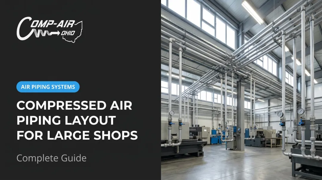
The Piping Network Structure
Most industrial systems follow a four-layer hierarchy:
- Risers — vertical mains rising from the compressor room
- Distribution headers — horizontal mains running across the facility
- Service pipes — branch lines serving individual work areas or bays
- Drops — final connections to specific tools or machines
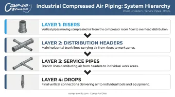
Each layer steps down in diameter as flow splits toward individual uses. Getting the sizing right at each level is critical — a bottleneck anywhere in the hierarchy creates pressure drop that compounds downstream.
Air Receiver (Storage Tank)
The receiver buffers demand spikes, stabilizes system pressure, and reduces compressor cycling. It also acts as a settling chamber where moisture drops out before air enters the distribution piping.
Receiver sizing should use a time-based storage formula rather than a universal ratio — the correct size depends on your compressor capacity, average demand, acceptable pressure band, and allowable on/off cycle frequency. Undersizing forces the compressor into short-cycling, which accelerates mechanical wear far faster than steady-load operation.
Comp-Air Ohio supplies ASME-certified receivers in 30, 60, and 80-gallon horizontal configurations for reciprocating compressor packages, with each unit equipped with a pressure gauge, relief valve, drain valve, and service valve as standard.
Air Treatment Components
Treatment equipment must be installed in the correct sequence:
- Aftercooler — removes the bulk of heat-of-compression moisture before air enters the receiver
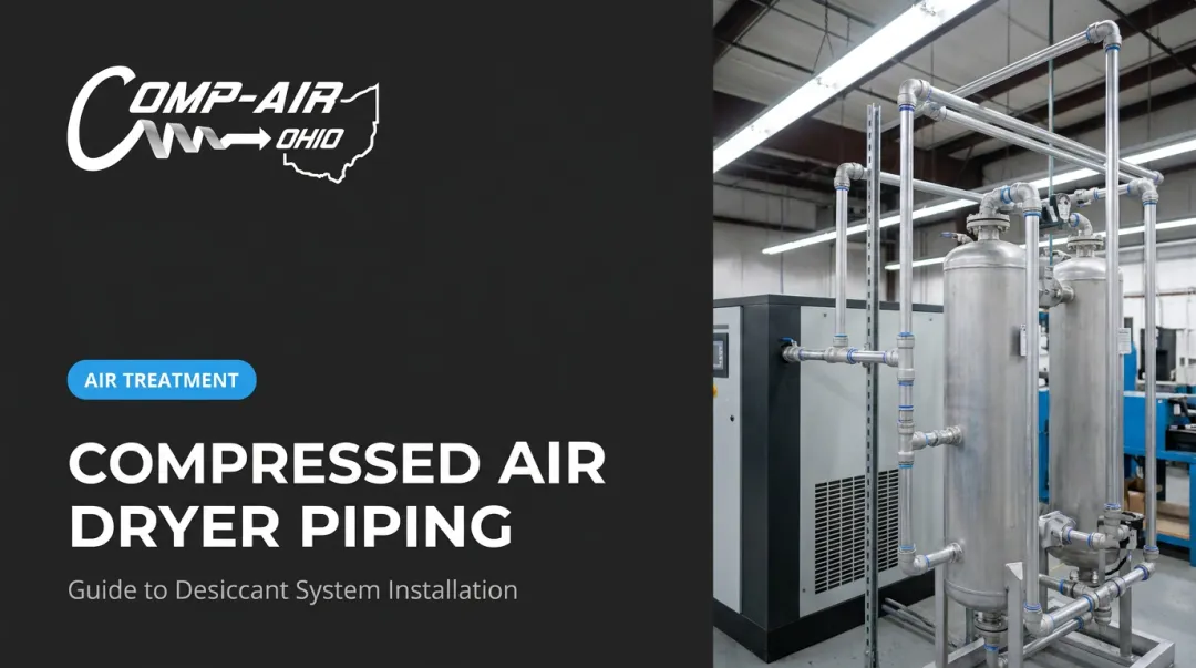
- Refrigerated or desiccant dryer — brings air to the required pressure dew point; refrigerated dryers (such as the Gardner Denver XGCY Series) deliver Class 4–5 air quality at 38°F/3°C dew point, while desiccant dryers like the ZEKS Eclipse ZPB Series reach Class 2 at -40°F or Class 1 at -80°F
- Coalescing filters — remove oil aerosols and fine particulates; ZEKS ZFF High Efficiency filters achieve 0.01 micron particulate removal with 0.01 ppm oil carryover
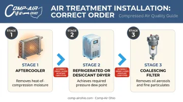
Sequence matters. A coalescing filter installed before a dryer will saturate quickly. A dryer installed before an aftercooler will be overwhelmed with liquid water.
Isolation Valves and Drip Legs
Isolation valves allow individual sections to be shut down for maintenance without taking the entire system offline. In a facility running multiple shifts, this capability is non-negotiable.
Drip legs are short vertical drops at low points in the piping where condensate collects by gravity. Without them, moisture travels with the airstream into tools and processes.
Automatic drains on drip legs prevent condensate buildup. Zero-loss electronic drains are the better choice over timer-based units — timer drains release air on a schedule regardless of whether condensate is actually present.
Air Quality Standards
For food and beverage, pharmaceutical, semiconductor, and medical device applications, ISO 8573-1:2010 defines purity classes for particles, water, and oil content. Gardner Denver's complete line of dryers, filters, and piping accessories — carried by Comp-Air Ohio — is designed to help facilities achieve specified ISO 8573-1 class ratings as part of an integrated system.
The Main Piping Configurations Explained
The topology you choose affects pressure consistency, flow capacity, redundancy, and how easily you can expand or maintain the system.
Linear (Dead-End) System
A single pipe runs from the compressor to the farthest point with no return loop. Pressure and flow drop progressively along the line — machines near the compressor are over-supplied, those at the far end are starved. Any leak or blockage affects every downstream user.
This configuration has one advantage: it's cheap to install. That's the only reason to consider it. In most cases, the long-term energy costs outweigh the lower installation price.
Branched System
A large-diameter central artery supplies multiple smaller branch lines. This works well for multi-zone facilities where different areas have different air quality requirements or operating schedules. The central artery must be generously oversized, and a secondary buffer tank at the end of the main artery helps manage demand surges from simultaneous zone starts.
Closed-Loop (Ring) System
Air flows in both directions around the loop to reach any drop point. This equalizes pressure throughout the network and effectively increases the system's flow capacity compared to a straight-line pipe of the same diameter.
The ring system is the most widely recommended configuration for single-facility industrial applications. For most Northern Ohio manufacturing facilities, Comp-Air Ohio specifies loop configurations as the standard starting point when designing a new distribution system.
Satellite System
A central artery feeds several individual closed loops — one per zone or building. This hybrid approach delivers a few practical advantages over a single facility-wide loop:
- Isolate entire zones for maintenance or off-hours energy savings
- Apply zone-specific air treatment where quality requirements differ
- Contain leak exposure when one area of production is shut down
Gridded System
Secondary cross-pipes within a loop create multiple parallel flow paths. This minimizes pressure drop to virtually any location and provides maximum redundancy. It's best suited to very large facilities with high, variable demand distributed across many points.
How to Size Your Compressed Air Distribution System
Demand Calculation and SCFM
Start by summing the CFM requirements of all tools and processes, then apply a simultaneity factor — not everything runs at once. Add a margin for future growth and unaccounted leakage.
Use SCFM (Standard Cubic Feet per Minute) rather than actual CFM for all calculations. SCFM normalizes flow to standard conditions (68°F, 14.5 psia, 0% relative humidity), making it the correct metric for comparing compressors, sizing piping, and specifying equipment.
Actual CFM shifts with site conditions — altitude, temperature, inlet pressure — so two compressors with different ACFM ratings may deliver identical SCFM output. Always spec and compare in SCFM.
Pressure Drop Limits
CAGI's pressure drop guidance sets the benchmark at no more than 10% total pressure drop between compressor discharge and the point of use, with piping velocity at 20 ft/s or lower to reduce turbulence.
Compensating for poor pipe sizing by raising compressor discharge pressure is not a solution — it's an ongoing energy tax.
Key Sizing Variables
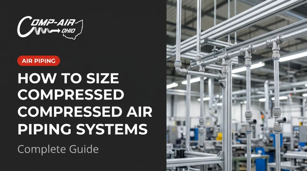
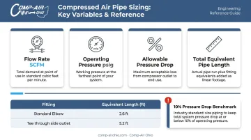
Four variables determine the required pipe diameter:
- Flow rate (SCFM) — your calculated total demand
- Operating pressure — system design pressure in psig
- Allowable pressure drop — stay within the 10% benchmark
- Total equivalent pipe length — actual pipe length plus equivalent length added by fittings
Fittings add meaningful resistance. Per CAGI handbook data, a standard 1-inch elbow adds approximately 2.6 feet of equivalent pipe length, and a 1-inch tee through the side outlet adds 5.2 feet. In a system with dozens of elbows and tees, this accumulated equivalent length can substantially inflate your effective pipe length calculation.
Once pipe diameter is confirmed, receiver sizing is the next calculation — because even a correctly sized pipe network can't compensate for a storage tank that can't buffer demand spikes.
Duty Cycle and Receiver Sizing
A 75% duty cycle means the compressor can run under load for 75% of any period (45 minutes per hour) without overheating. If your demand profile requires more continuous output than the duty cycle allows, the receiver must carry the difference.
Signs of an undersized receiver:
- Compressor short-cycles repeatedly to meet demand
- Valves, rings, and motor starters wear out ahead of schedule
- Pressure at point of use drops during high-demand events
Plan for Expansion
Over-sizing pipe by one nominal diameter at installation costs modestly more upfront. Retrofitting becomes expensive once walls, equipment, and ceiling infrastructure are locked in — both in materials and operational disruption.
Design Best Practices to Minimize Pressure Drop
Use a Loop and Feed It Correctly
When feeding a loop from a storage receiver, use a feed pipe at least one size larger than the loop pipe itself. A feed pipe bottleneck defeats the purpose of the loop's bidirectional flow advantage.
Manage the Last 30 Feet
The "Dirty 30" — the final 30 feet of piping and connectors at the point of use — is where the majority of leaks and pressure losses occur. Specific practices:
- Limit quick-disconnect couplings to portable hand tools and paint guns only
- Use hard-pipe or hose-barb connections for stationary equipment
- Minimize elbows and tees throughout the run
- Keep drop legs vertical and properly sized for the tool's peak demand
Conduct a Leak-Down Audit
A simple baseline test: record system pressure at end of shift, check again before the next shift starts. If overnight pressure drop exceeds 10% of starting pressure, a formal leak detection survey is overdue.
DOE Tip Sheet #3 reports leaks often waste 20–30% of compressor output. In a facility spending $50,000 per year on compressed air energy, that's $10,000–$15,000 disappearing through fittings, joints, and hoses.
Finding those leaks starts with the right tool. Ultrasonic leak detectors are the most effective method for locating leaks while equipment is running — the high-frequency sound of escaping air is detectable even in noisy plant environments.
Comp-Air Ohio performs full compressed air system assessments for Northern Ohio facilities — identifying pressure drop points, locating leaks, and recommending piping configurations matched to your actual demand. Call (440) 237-6700 to get started.
Pipe Material Selection and Maintenance
Comparing the Main Options
| Material | Advantages | Disadvantages |
|---|---|---|
| Aluminum | Corrosion-free, lightweight, push-to-connect fittings, leak-resistant, lifetime warranty on Gardner Denver Quick-Lock/Big-Lock systems | Higher initial cost than iron |
| Copper | Corrosion-resistant, smooth bore, durable | Requires soldering skill; labor-intensive |
| Black iron/steel | Strong, widely available, familiar | Internal rust contaminates air; threaded joints leak over time |
| Flexible PEX | Easy installation | Lower pressure durability; not suitable for industrial applications |
| PVC | ❌ Never use for compressed air | Becomes brittle with UV and age; OSHA documented a PVC pipe explosion where a fragment traveled 60 feet and embedded in plywood |
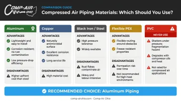
Gardner Denver's Quick-Lock system (14mm–63mm, rated 300 PSI / 300°F) and Big-Lock system (70mm–273mm, same pressure/temperature rating) both feature double O-ring seals and a lifetime leak-free guarantee. Compared to threaded black iron pipe, installation time drops considerably: no threading, cutting dies, or thread sealant required.
Threaded Joint Sealing
Legacy systems and mixed installations still rely on threaded connections in places. Where that's the case, pipe dope (thread sealant compound) provides a more reliable seal than PTFE tape. Aluminum push-to-connect systems largely eliminate this concern by design.
Ongoing Maintenance Priorities
- Schedule leak detection surveys periodically — not just when problems appear; ultrasonic detectors work while the system is pressurized and running
- Drain drip legs and condensate traps on a regular schedule; automatic zero-loss drains reduce manual attention requirements
- Replace filter elements based on differential pressure readings — ZEKS ZFF filters use a tricolor gauge for timing; Grade A activated carbon filters max out at 6 months or 4,000 hours regardless of pressure drop
- Inspect isolation valve seating integrity annually; a valve that won't fully close makes any downstream maintenance work unnecessarily risky
- Use genuine OEM parts and lubricants — Gardner Denver's AEON 9000TH (rotary screw) and AEON AC series (reciprocating) preserve warranty coverage and keep the system performing to its original specifications
Frequently Asked Questions
What is a compressed air distribution system?
It's the network of pipes, fittings, valves, dryers, filters, and accessories that carries compressed air from the compressor to each point of use throughout a facility. A well-designed system delivers the required flow and pressure at every drop point while minimizing energy loss and contamination.
Which is better, CFM or SCFM?
SCFM is the correct metric for distribution system design. It normalizes flow to standard conditions (68°F, 14.5 psia, 0% relative humidity), which makes it valid for comparing compressors, sizing piping, and specifying equipment across different sites. CFM varies with local temperature and pressure, so it can't be used reliably for system comparisons.
What is a 75% duty cycle?
A 75% duty cycle means the compressor can run under load for 75% of any given time period (45 minutes per hour, for example) without overheating. Consistently exceeding this through an undersized receiver or sustained high demand accelerates wear on valves, motor starters, and internal components.
What is the best pipe material for a compressed air distribution system?
Aluminum is widely preferred for modern industrial installations. It's corrosion-resistant, lightweight, easy to modify, and available in push-to-connect systems with lifetime leak-free guarantees. PVC should never be used for compressed air — it becomes brittle over time and can fail explosively.
What causes pressure drop in a compressed air distribution system?
The main contributors are undersized pipe diameter, excessive total pipe length, too many elbows and tees, quick-disconnect couplings, leaks, and clogged filter elements. Pressure drop compounds across every component, so poor sizing or layout decisions made early can create cascading efficiency losses throughout the system.
How do you know if your system needs to be redesigned?
Key warning signs include tools underperforming at the far ends of the line, frequent compressor cycling, energy costs rising without increased production, audible or visible leaks, and moisture showing up at points of use. Any one of these warrants an audit — multiple together indicate a system that's overdue for a redesign.