Skip the planning phase and you pay for it later. Undersized pipes cause pressure drops at far workstations, improper slope leads to moisture pooling and tool damage, wrong materials (especially PVC) create genuine safety hazards, and unplanned layouts make future expansion costly. According to the Compressed Air Challenge, leaks alone can waste 20–30% of a compressor's output in poorly maintained industrial systems.
This guide walks through site assessment, material selection, layout configuration, step-by-step installation, and validation — covering every phase of a large shop compressed air piping project.
Key Takeaways
- Complete a full-shop schematic and total CFM calculation before purchasing any materials
- Choose a ring/loop layout for large shops — it equalizes pressure at all drops
- Use aluminum or black steel pipe only — PVC is prohibited for compressed air distribution
- Slope all horizontal runs toward drain points to prevent moisture accumulation
- Pressure test the system and confirm acceptable pressure drop at the farthest outlets before commissioning
Compressed Air Piping Layout for Large Shops
A successful large shop installation follows a logical sequence: assess site requirements → select configuration and materials → install the distribution network → validate the system. Rushing or skipping any phase creates problems that are expensive to correct once pipes are in place.
Prerequisites: Site Assessment and Safety Considerations
Before installation begins, map the following:
- Facility dimensions and floor plan
- Compressor location and proposed main trunk routes
- Total number of usage points and workstations
- Distance from the compressor to the farthest drop
- Whether different zones (fabrication vs. paint) require different air quality classes per ISO 8573-1:2010
ISO 8573-1 classifies compressed air quality across three contamination types (particles, water, and oil), expressed as a three-part notation such as 3:4:2. General fabrication typically falls around Class 3–5, while paint booths and food processing require significantly cleaner air.
Determine zone-specific quality requirements before sizing any pipe.
Safety non-negotiables:
- All piping must be rated for the system's maximum operating pressure
- PVC pipe must never be used in compressed air distribution — Oregon OSHA Fact Sheet FS-44 explicitly states PVC can shatter or explode under pressure or external force, and ASME B31.3 prohibits PVC and CPVC in compressed air service due to brittle failure risk
- Follow applicable OSHA standards (29 CFR 1910 Subpart M covers compressed gas and compressed air equipment) and local mechanical codes
Do not begin installation without a completed system schematic showing all pipe routes, drop locations, and a total CFM demand calculation for all tools running simultaneously at peak demand.
Pipe Materials and Sizing for Large Shops
Material comparison:
| Material | Pros | Cons |
|---|---|---|
| Aluminum | Lightweight, corrosion-resistant, fast to install with compression fittings, smooth bore for low pressure drop | Higher upfront cost than black steel |
| Black Steel | Strong, widely available | Requires threading, prone to internal rust scale that contaminates air and reduces effective diameter |
| Copper | Clean, corrosion-resistant | Labor-intensive to solder at scale, higher cost |
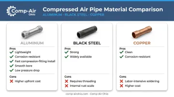
Aluminum systems are now the preferred choice for industrial installations. Comp-Air Ohio supplies Gardner Denver's Quick-Lock and Big-Lock aluminum piping systems covering ½" through 10" diameter, rated for 300 PSI and 300°F, with a lifetime leak-free guarantee. Manufactured from marine-grade aluminum — one-tenth the weight of equivalent steel — they deliver the lowest pressure drops of any common piping material.
Pipe sizing fundamentals:
Sizing is determined by total system SCFM demand and total pipe run length. Key velocity guidelines from Compressed Air Best Practices:
- Compressor room headers: ≤ 20 ft/sec
- Distribution headers leaving the compressor room: ≤ 30 ft/sec
At 100 psig, 100 SCFM through 1" pipe over 1,000 feet causes approximately 27.9 psi pressure loss — the same flow through 2" pipe causes only 0.77 psi. Consult a pipe sizing chart using your system's total SCFM and longest run length before purchasing. If you undersize the main trunk, no amount of additional drops or fittings will recover that lost pressure.
Layout configurations:
Once your pipe material and diameter are confirmed, layout configuration determines how pressure distributes across the shop:
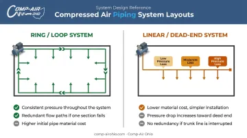
- Ring/loop system: The main line circles the shop perimeter and reconnects near the compressor, feeding drops from two directions. Pressure equalizes across all outlets, and individual zones can be isolated for maintenance without shutting down the entire system. Preferred for large shops.
- Linear/dead-end system: A single trunk runs from the compressor with drops along the way. Simpler and cheaper to install, but pressure falls progressively at stations farthest from the source. Use only for small layouts or where a loop isn't structurally feasible.
How to Install Compressed Air Piping in a Large Shop
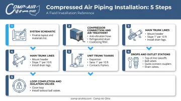
Installation follows a defined sequence. Skipping steps — particularly the system schematic or the anti-vibration compressor connection — leads to pressure drops, moisture contamination, and vibration-induced pipe failures that are expensive to diagnose after the fact.
Step 1 — Finalize the System Schematic
Draw the layout to scale on a facility map. Mark:
- All drop locations and main trunk routes
- Expected pipe lengths and fitting counts
- Valve locations and zone boundaries
Use this drawing to generate a complete materials list before purchasing anything. Comp-Air Ohio's team can assist Northern Ohio facilities with system design and equipment sizing, ensuring the compressor output and distribution system are properly matched from the start.
Step 2 — Install the Compressor Connection and Air Treatment
- Connect the compressor to the distribution network using a flexible anti-vibration hose — this isolates compressor vibration from fixed piping
- Install a refrigerated air dryer immediately downstream of the compressor aftercooler — this is the primary moisture removal point
- Install a coalescing filter downstream of the dryer to capture oil aerosols and particulates
- Position filter/regulators where they're accessible for routine maintenance
Comp-Air Ohio carries ZEKS HeatSink refrigerated dryers from 10 to 2,400 SCFM and Gardner Denver X Series large-capacity dryers from 1,800 to 24,000 CFM, covering the full range of large shop requirements.
Step 3 — Run the Main Trunk Lines
With the compressor connection and air treatment in place, the distribution run begins at the main trunk. Mount the header pipe at a consistent height along walls or overhead using pipe hangers, then:
- Slope all horizontal runs 1" per 10 feet in the direction of airflow toward low-point drain legs — this is the figure cited by Compressed Air Best Practices for industrial systems
- Use rated elbows at corners and tee fittings at drop points
- At each low point, install a drain leg with a drain valve to purge accumulated condensate
Step 4 — Install Drops and Outlet Stations
Each drop should:
- Originate from the top of the main line — prevents water from migrating into the drop
- Terminate in a ball shutoff valve and quick-connect coupler at working height (typically 36–48" above finished floor)
- Include a drain valve at the bottom of each drop leg to purge moisture
For large shops with many drops, automatic timed drain valves eliminate the need for manual purging. Comp-Air Ohio offers electronic timer drain valves and zero-loss drain valves (ZEKS CZLD Series, 200–53,000 SCFM) that expel no compressed air when cycling.
Step 5 — Complete the Loop and Install Isolation Valves
- Connect the return end of the main trunk back near the compressor outlet to close the loop
- Install lockout ball valves at the entry point of each zone or branch — these allow sections to be safely isolated for maintenance without shutting down the entire shop
- Ensure all zone isolation valves support LOTO (lockout/tagout) procedures per OSHA requirements
Post-Installation Checks and Validation
Pre-Pressurization Checks
Before pressurizing:
- Confirm all compression fittings are tightened to manufacturer spec
- Verify all pipe hangers are secured and slope is correct at low points
- Ensure no debris or pipe shavings remain inside the system
- Close all outlet points in the piping system
Leak Test Procedure
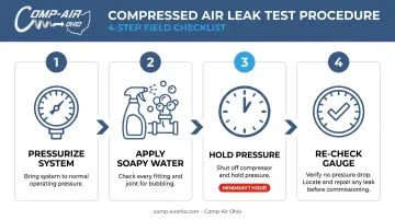
- Pressurize the system to operating pressure
- Apply soapy water to every fitting and joint — bubbling indicates a leak
- Shut off the compressor and hold system pressure for at least one hour
- Re-check the pressure gauge — any pressure drop indicates a leak that must be located and repaired before commissioning
Shut off the compressor and hold system pressure for at least one hour — the Gardner Denver Quick-Lock commissioning procedure specifies a 1-hour hold at full working pressure as the minimum acceptance standard
Pressure Drop Validation
With the system under load — tools operating at the farthest drops — measure pressure at those outlets and compare to supply pressure. The Compressed Air Challenge states that a properly designed system should have pressure loss of no more than 10% of compressor discharge pressure from receiver to point of use.
If measured pressure drop approaches or exceeds that threshold, review the system design for these common causes:
- Undersized trunk line — the main header may need upsizing to the next pipe diameter
- Linear layout — converting to a ring (loop) system reduces one-way pressure drop significantly
- Excess fittings — audit all elbows, tees, and reducers; each adds equivalent pipe length and resistance
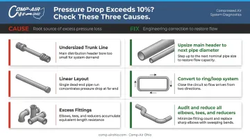
Common Compressed Air Piping Problems and Fixes
Most large-shop piping problems trace back to a handful of root causes. Here's how to identify each one and fix it without overhauling your entire system.
Issue 1: Pressure Drop at Remote Workstations
Problem: Tools at farthest drops underperform — impact wrenches lose torque, spray guns produce uneven finishes.
Likely causes:
- Main trunk line is undersized for total CFM demand
- Dead-end linear layout used instead of a ring system
- Excessive fittings creating unnecessary flow restriction
Fix: Convert to a ring/loop layout if structurally feasible; upsize the main trunk to the next pipe diameter; audit and minimize unnecessary fittings.
Issue 2: Moisture and Water at Tool Connections
Problem: Water or rust particles discharge from couplers, tools corrode internally, finish quality from spray equipment is compromised.
Likely causes:
- No refrigerated dryer installed, or dryer is undersized for actual system SCFM
- Horizontal pipe runs are level rather than sloped
- Drop drain valves are not being opened regularly
Fix: Install or upgrade the refrigerated dryer at the compressor outlet; verify pipe slope and correct any level runs; install automatic timed drain valves at all drop leg low points.
Issue 3: Air Leaks at Fittings
Problem: Audible hissing from joints, overnight pressure loss without tool use, higher-than-expected compressor run cycles.
Likely causes:
- Compression fittings hand-tightened but not torqued to manufacturer spec
- Threaded connections improperly sealed
- Dissimilar metals in contact corroding at joints
Fix:
- For threaded connections, follow manufacturer-specified sealant requirements. Some manufacturers, including Parker for pneumatic components, caution against relying solely on PTFE tape.
- For compression fittings, follow torque specifications precisely rather than estimating by hand.
- Use zone isolation valves to locate and contain leaking sections without a full shop shutdown.
Pro Tips for Installing Compressed Air Piping in Large Shops
Follow these four practices to avoid the most common — and costly — installation mistakes:
Oversize the main trunk line by one pipe diameter beyond current demand, and stub out capped drops at future workstation locations during installation. Adding capacity later is far more expensive than planning for it upfront. Aluminum modular piping systems make future modifications straightforward.
Install lockout-capable ball valves at every zone. In industrial environments, isolating a pipe section for repair without a full system shutdown is critical. All zone isolation points should support LOTO procedures to stay compliant with OSHA lockout/tagout requirements.
Update your as-built documentation once installation is complete — record actual pipe routes, valve locations, drop IDs, and pipe sizes, then keep this drawing on-site. For large shops, it becomes the first reference during troubleshooting, expansions, and compliance inspections.
Bring in a professional for complex systems. Multi-zone layouts, ISO 8573-1 air quality mandates (food, pharmaceutical, medical), or high simultaneous demand are worth a professional assessment. Comp-Air Ohio provides full system guidance for industrial facilities across Northern Ohio, from compressor sizing through distribution design. Contact their team at (440) 237-6700 to arrange a consultation.
Conclusion
Compressed air piping layout quality in a large shop directly determines whether every workstation receives clean, dry, properly pressured air consistently. Poor installation choices — wrong materials, undersized pipe, missing air treatment — don't cause isolated problems; they compound into ongoing downtime, equipment corrosion, and expensive rework.
Before your system goes live, make sure you've covered the fundamentals:
- Plan the layout fully before purchasing materials or cutting pipe
- Follow the installation sequence without shortcuts — especially air treatment placement
- Validate flow, pressure drop, and leak integrity before full operation
If your system serves multiple zones, has stringent air quality requirements, or is being built for long-term industrial use, bring in a specialist early. Comp-Air Ohio has been designing and installing compressed air systems across Northern Ohio since 1977 — getting that input at the planning stage almost always costs less than correcting problems after commissioning.
Frequently Asked Questions
What is the best pipe for compressed air in a shop?
Aluminum and black steel are the two most common choices. Aluminum is increasingly preferred for its corrosion resistance, light weight, and fast installation with compression fittings. PVC must never be used for compressed air regardless of pressure rating — it becomes brittle over time and can shatter under pressure, creating a serious safety hazard.
What size air line should I run in my shop?
Pipe size depends on total SCFM demand and run length. Use a pipe sizing chart based on your system's total SCFM and longest run, sizing for velocity (20–30 ft/sec in distribution headers) and allowable pressure drop rather than generic diameter ranges. Have a qualified distributor verify your sizing before purchasing materials.
What is the difference between a ring/loop system and a linear system for a large shop?
A ring system routes the main line around the shop and connects back to the supply, feeding each drop from two directions and equalizing pressure throughout. A linear system runs to a dead end and causes progressively lower pressure at the farthest outlets. Ring systems are strongly preferred for large shops.
How do I prevent moisture buildup in compressed air lines?
Three practices work together: install a refrigerated dryer at the compressor outlet, slope all horizontal pipe runs (1" per 10 feet) toward drain legs, and install automatic drain valves at each drop's low point to purge accumulated condensate.
How much pressure drop is acceptable in a compressed air distribution system?
The Compressed Air Challenge recommends keeping total pressure loss under 10% of compressor discharge pressure from receiver to point of use. On a 100 PSI system, that's less than 10 PSI — ideally much less. Drops approaching this threshold point to undersized piping, an inefficient layout, or excessive leakage.