
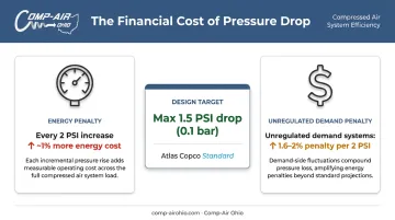
The stakes are real. Every 2 PSI increase in discharge pressure raises energy consumption by approximately 1% in 100 PSI systems — meaning avoidable pressure drop directly hits your operating budget.
Sizing compressed air piping isn't just about picking a diameter. Results depend on peak CFM demand, total equivalent pipe length, allowable pressure drop, air velocity, layout design, and fitting allowances. This guide covers each step and the most costly mistakes to avoid.
Key Takeaways
- Size pipe diameter based on peak simultaneous CFM demand, not average usage
- Account for every fitting, elbow, and valve by converting them to equivalent pipe lengths
- Keep pressure drop between compressor and furthest point of use within 1.5 PSI — the accepted industry benchmark
- Distribution mains should target 30 ft/s maximum air velocity per Compressed Air Challenge guidance
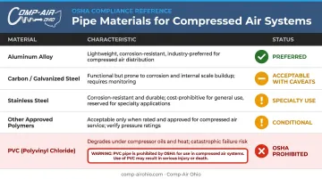
- Never use PVC for compressed air — OSHA prohibits it due to brittle failure risk
- When calculations fall near a pipe size's upper CFM limit, size up
How to Size Compressed Air Piping: Step-by-Step
Step 1: Determine Your Maximum CFM Requirements
Airflow demand — measured in standard cubic feet per minute (SCFM) — is the primary driver of pipe diameter. Sizing must be based on peak simultaneous demand, not average usage. Average flow hides short surge events from pneumatic cylinders, dust collectors, and diaphragm pumps that cause significant pressure drop at remote points of use.
To calculate peak demand:
- List all air-consuming equipment in the facility with their individual CFM requirements
- Identify simultaneous users — which tools or processes could realistically run at the same time
- Sum the CFM for all simultaneously operating equipment
- Handle burst-demand equipment separately — pneumatic cylinders and dust collector blow-down valves create short high-demand spikes that are better managed with point-of-use receiver tanks than by oversizing the entire distribution system

Your baseline input is verified compressor output data from the manufacturer nameplate or documentation. Accurate source data is essential: inaccurate inputs produce unreliable sizing results regardless of how carefully the rest of the calculation is done.
Kaeser recommends measuring demand over at least 7 days using flow meters or data logging for existing systems, specifically to capture production variation and true peak events.
Step 2: Calculate Total Equivalent Pipe Length
Pressure drop accumulates across every fitting, elbow, tee, and valve in the system, not just straight pipe runs. Sizing from straight-run measurements alone consistently produces undersized distribution mains.
How to calculate equivalent pipe length:
- Measure all straight pipe runs from the compressor to the most distant point of use
- Add equivalent lengths for each fitting type using a fitting loss table (CAGI Chapter 8 includes Table 8.17 — Loss of Pressure through Screw Pipe Fittings, expressed as equivalent lengths of straight pipe)
- Sum actual straight-run length + all fitting equivalent lengths = Total Equivalent Pipe Length
As a reference point: a standard 90° elbow in 2" Schedule 40 pipe adds approximately 5 feet of equivalent length, while a long-radius 90° elbow in the same pipe adds roughly 3.4 feet. Sharp elbows add significantly more resistance than long-radius alternatives , worth factoring in during layout planning.
Loop system note: In a closed-loop (ring main) layout, air travels from two directions to any point of use. This reduces effective flow in each direction and cuts pressure drop substantially compared to a single trunk-line layout. For loop calculations, work with the flow and resistance characteristics of each leg rather than applying a single equivalent length rule.
Step 3: Establish Operating Pressure and Allowable Pressure Drop
Most industrial compressed air systems operate between 90–125 PSI at the compressor discharge, with pneumatic tools and equipment typically requiring 90–100 PSI at the point of use. The gap between those two numbers is your allowable pressure drop budget.
Why this matters financially:
- Every 2 PSI increase in discharge pressure raises energy consumption by approximately 1% at full output
- In systems where unregulated demand is 30–50% of total air consumption, the combined effect reaches 1.6–2% per 2 PSI increase
- That penalty runs continuously — every hour the compressor operates at elevated pressure to compensate for distribution losses
Atlas Copco's published benchmark states that fixed compressed air networks should be dimensioned so pipe pressure drop does not exceed 0.1 bar (approximately 1.5 PSI) between compressor and point of use. Use this as your design target.
Exceeding that threshold means your compressor runs at a higher setpoint to compensate, and that cost accumulates fast at industrial operating hours.
Step 4: Apply the Sizing Formula or Use a Pipe Sizing Chart
With peak CFM, total equivalent pipe length, and allowable pressure drop established, solve for minimum pipe diameter using one of two approaches.
Formula-based approach:
The velocity-based sizing formula published by EXAIR is:
- A = 144 × Q × Pa / (V × 60 × (Pd + Pa))
- D = √(A × 4 / 3.14)
Where A = pipe bore area (sq. in.), Q = flow in SCFM, Pa = atmospheric pressure (14.7 PSI at sea level), V = target air velocity (ft/s), and Pd = line pressure.
Chart-based approach (practical alternative):
Published pipe sizing charts — such as those from Dixon for ANSI standard pipe at 100 PSI — allow you to cross-reference CFM and total equivalent pipe length to find minimum recommended diameter. As a reference point, a 4" Schedule 40 pipe at 100 PSI carries approximately:
| Equivalent Length | Approximate Capacity |
|---|---|
| 100 ft | 2,140 SCFM |
| 200 ft | 1,510 SCFM |
| 500 ft | 955 SCFM |
Key rule: When your calculation result lands near the upper CFM limit for a given pipe size, size up. The incremental material cost is small compared to re-piping later or running the compressor at elevated pressure indefinitely.
Key Variables That Affect Compressed Air Pipe Sizing Results
Even with the correct formula or chart, four variables can significantly shift the sizing outcome if not properly evaluated.
Air Velocity
Velocity is one of the most overlooked factors in pipe sizing. The Compressed Air Challenge specifies the following velocity ceilings for main headers:
- Compressor room headers: 20 ft/s maximum
- Distribution headers leaving the compressor room: 30 ft/s maximum
Exceeding these limits creates turbulence, backpressure, noise, and moisture carryover. Compressed air carries water droplets in the air stream and water films along pipe walls — high velocity accelerates that transport directly into end-use equipment.
If your pressure drop calculation suggests a smaller diameter is acceptable but velocity would exceed these limits, the velocity limit governs — size up.
Pipe Material
Pipe material determines the friction coefficient of the pipe wall, which directly affects pressure drop per foot of run. The practical hierarchy:
- Aluminum alloy (purpose-rated for compressed air): Smooth, corrosion-resistant bore with superior pressure-differential characteristics — the preferred choice for most plant air distribution systems
- Schedule 40 carbon steel / galvanized steel: Widely used in industrial plants at 100–125 PSI service, but corrosion and scale accumulate over time, narrowing effective bore and increasing friction
- Stainless steel: Used in food, pharmaceutical, and textile plants where contamination avoidance justifies the cost premium
- PVC: OSHA explicitly states PVC pipe shall not be used to transport compressed air — brittle failure can shatter the pipe and send plastic fragments outward. This is a safety exclusion, not a material preference
- Other polymer systems: Only use polymer pipe that is specifically approved and marked for compressed air service and compliant with applicable building codes
System Layout: Loop vs. Straight-Run
A closed-loop (ring main) layout routes air from two directions to any point of use. Because each leg carries only a portion of the total flow, pressure drop is dramatically lower than a single-trunk straight-run system.
For facilities planning new distribution systems, a ring main layout is worth the additional installation complexity — particularly in larger plants where multiple end-users are distributed across wide floor areas.
Fittings, Valves, and Connections
Layout decisions don't end with pipe routing. High-resistance fittings create pressure drop that is invisible to designers who only account for straight pipe length. Best practices:
- Use full-port ball valves — they don't reduce pipe diameter and add minimal resistance
- Butterfly valves are acceptable when seal materials are compatible with compressed air, moisture, and compressor lubricant
- Avoid standard gate valves and sharp reducers in distribution mains
- Take drops from the top of the air main, not the bottom — this prevents contamination carryover to tools during air treatment failures
- Install drip legs at low points in mains for condensate drainage
What You Need Before Sizing Your Compressed Air Piping System
Sizing accuracy depends entirely on input quality. Undersized or oversized systems trace back to missing or incorrect data at this stage.
Gather the following before running any calculations:
- Compressor output specs: Verified SCFM/ACFM, discharge pressure (PSI), and any planned future capacity — your compressor documentation or dealer should supply this directly
- Facility piping schematic: Locations of all air-consuming equipment, distances from the compressor, number of fittings, and direction changes in each run
- Zone usage patterns: Equipment grouped by area with simultaneous usage rates noted — this drives demand diversity calculations
- Future expansion plans: If the facility will add equipment or expand operations within 5–10 years, include that anticipated demand now — upsizing pipe during initial installation costs far less than re-piping later
Comp-Air Ohio's compressed air audits cover exactly this kind of pre-installation evaluation: assessing current demand, identifying inefficiencies, and recommending system improvements before a new installation is specified.
Common Mistakes and Warning Signs in Compressed Air Pipe Sizing
Three mistakes account for most undersized systems:
Sizing for average demand instead of peak demand. Average flow calculations miss surge events from pneumatic cylinders, dust collectors, and diaphragm pumps — and those surges are what expose undersized pipe.
Ignoring equivalent lengths for fittings. Elbows, tees, and valves add measurable resistance. Systems sized for straight runs only look correct on paper but consistently underperform in the field.
Not planning for future expansion. If your flow calculations land near the upper CFM limit for a given pipe size, size up. The cost difference at installation is minimal; the cost of a field correction is not.

A CAGI case study illustrates the cost of getting this wrong: a 4" pipe serving 2,909 SCFM created a 10 PSI pressure drop, requiring a full replacement with 6" pipe — an avoidable expense with proper peak-demand sizing.
Warning Signs Your Piping Is Wrongly Sized
Undersized piping shows up as:
- Pressure differential greater than 1.5 PSI between the compressor outlet and the most distant point of use
- Pneumatic tools operating sluggishly or inconsistently
- Compressor cycling more frequently than expected or running continuously to maintain setpoint pressure
Oversized piping rarely creates performance problems, but it increases material and installation costs and slows system pressurization on startup. It's also not a substitute for a properly sized receiver tank — if additional air storage is the real need, that's where the investment belongs.
Frequently Asked Questions
How do you size a compressed air system?
Start by calculating peak CFM demand across all simultaneously operating air-consuming equipment, then match compressor output to that demand. Size distribution piping to deliver air with no more than 0.1 bar pressure drop to the furthest point of use.
How do you size pipes for a compressed air system?
Four steps cover the process:
- Determine peak CFM demand
- Calculate total equivalent pipe length, including all fittings and valves
- Establish your allowable pressure drop budget
- Use a sizing formula or published chart to find the minimum diameter, sizing up if results fall near the upper CFM boundary
How much CFM can go through a 4-inch pipe?
At 100 PSI, a 4" Schedule 40 pipe carries approximately 2,140 SCFM over 100 feet of equivalent length, 1,510 SCFM over 200 feet, and around 955 SCFM over 500 feet. Capacity drops significantly with longer runs and higher fitting counts.
What is the maximum allowable pressure drop for compressed air piping?
Atlas Copco's benchmark for fixed networks is a maximum of 0.1 bar (approximately 1.5 PSI) between the compressor and the most distant point of use. Exceeding that threshold forces the compressor to run at higher discharge pressure. The DOE confirms this costs roughly 1% more energy per 2 PSI increase.
What pipe material is best for compressed air systems?
Aluminum alloy piping designed specifically for compressed air is the preferred choice for most plant air distribution systems — smooth bore, corrosion-resistant, and low friction across the system's lifetime. PVC must never be used; OSHA prohibits it due to the risk of brittle failure and high-velocity fragment ejection.
What air velocity should I design for in compressed air distribution piping?
The Compressed Air Challenge specifies 20 ft/s maximum for compressor room headers and 30 ft/s maximum for distribution mains leaving the compressor room. Exceeding these limits causes turbulence, elevated pressure drop, and moisture carryover into end-use equipment. If velocity limits conflict with pressure drop calculations, velocity governs — size up.
Comp-Air Ohio's team provides complete compressed air system design and turnkey installations across Northern Ohio, including piping specification using Gardner Denver Quick-Lock and Big-Lock aluminum piping systems — from ½" up to 10" diameter — as part of a full system solution.